e2b calibration, A Transcat Company
e2b calibration, a Transcat Company, was founded in the 1990’s in association with Haitek Solutions, an ERP software developer. Since its origin, e2b calibration was driven to help customers enable technology, maximize profitability, and streamline operations in order to make critical decisions, build better products, provide better services, and exceed expectations.
After its acquisition in September 2022, e2b calibration joined the leading nationwide calibration services team at Transcat as its Transcat Cleveland Calibration Lab. The following services that you relied upon e2b calibration to provide are now available to you through Transcat.
Accredited Calibration Services – Now Transcat’s Cleveland Calibration Lab
The Transcat Cleveland, OH, Calibration Lab is a climate-controlled, state-of-the-art laboratory ISO/IEC 17025 and ANSI/NCSL Z540-1 accredited calibration and repair laboratory. The Cleveland Lab specializes in providing a full scope of calibration services for a broad range of industries, including Ground Support Equipment services for the aviation Industry. With unmatched quality systems and procedures, the Transcat Cleveland Lab offers the following calibration services:
- Ground Support Equipment (GSE) certification, calibration, maintenance, and repair services
- Electrical and electronic instrument calibration
- RF and microwave calibration
- Pressure calibration for gauges and transducers
- Vacuum calibration
- Torque calibration
- Force calibration for tension and compression
- Mass flow calibration
- Temperature and Humidity calibration
- Physical-dimensional calibration
Additional benefits of working with the Transcat Cleveland Lab:
- 5-7 day turnaround on most items
- Pick-up and delivery services available in most areas
- ANAB Accreditation audits include full assessment to ISO-17025: 2005 and ANSI/NCSL Z-540-1-1994
- Standards traceable to NIST, equivalent national or international sources, or physical constants, as appropriate
- Test Uncertainty Ratio (TUR) of 4:1 or better is typical
- Records of the history of each calibration standard
- Calibration tolerances based on manufacturer’s specifications or customer requirements
- Calibrated items labeled and the calibration access sealed where appropriate
- Proactive customer notification for any out-of-tolerance conditions discovered in our in-house asset calibration recall system
For detailed information on the full suite of calibration services available from Transcat, click here.
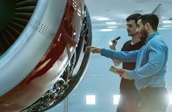
GSE Services
At Transcat, we’re proud to offer GSE certification, calibration, maintenance, and repair services for the aviation and aerospace industries. We ensure that critical ground support equipment is in compliance, providing calibration and GSE services for Part 145 MROs, Part 135 FBOs, and Part 91 Operations, both in-lab in our Cleveland Calibration Lab and on-site nationwide. As a Tronair Authorized Service Center and a Unitron Authorized Service Center, the Transcat Cleveland Lab is especially qualified to offer maintenance and repair services to a wide array of critical ground support equipment, including hydraulic power units, cabin pressure units, ground power units, aircraft jacks, engine slings, and more.
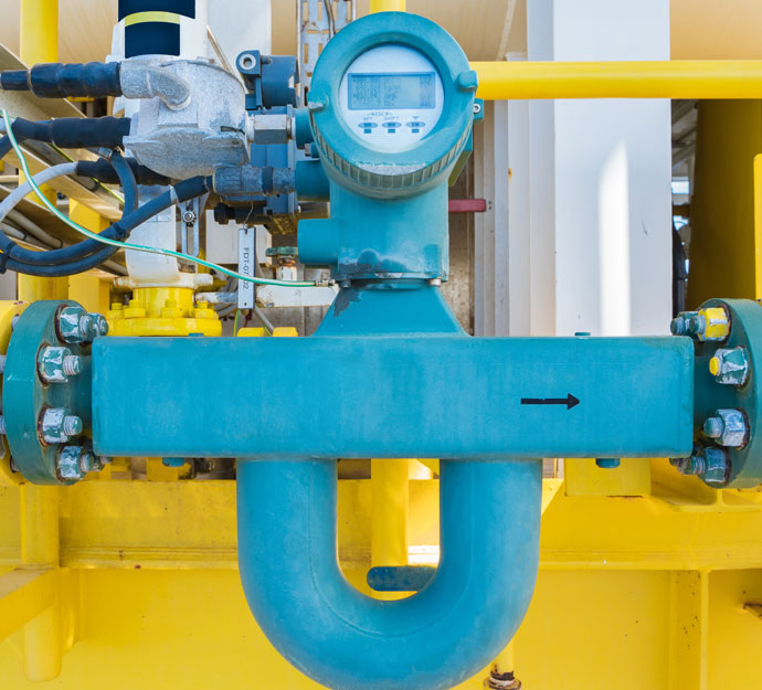
Flow Meter Calibration
Over time, flow meters are prone to internal surface deposits, contamination, contact with chemicals, and general wear and tear from external influences such as temperature, pressure, and vibration – to name a few. These factors can cause flow meters to drift, reducing the accuracy of the equipment and hindering its performance. Transcat offers specialized calibration expertise for flow meters and a full range of mass flow meter calibration and repair services for all popular flow meter models and brands. Our calibration expertise includes the following:
- ISO-17025: 2017 Registered with ANAB
- ANSI/NCSL Z540-1-1994 Certified
- NIST Traceable Wide scope of ISO/IEC 17025 accreditation
- Unmatched quality systems
- Extensive capabilities across all categories of instruments
- On-site service capability
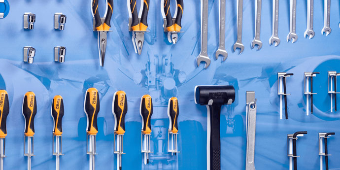
Shadow Board Design & Production
The team at the Transcat Cleveland Lab has the capabilities to produce custom Shadow Boards for special workplace situations, individual employee tool drawers, or boards identical to your production lines. Our team will assist you in choosing the correct material for your application so your boards can last for over 10 years, depending on use. With the use of our special design software, our team can customize each Shadow Board by size, color coding system, custom logos, or text for tool identification. Save time with an organized and tidy workstation and improve your productivity and efficiency with Shadow Boards from the Transcat Cleveland Lab.